CAN Bus Explained: How Telematics Unlocks Vehicle Data
Today’s fleet management relies on precise, real-time data to optimize operations, cut costs, and ensure vehicle safety.Every contemporary car contains a strong network that manages data generation. This technology is known as the CAN bus, or Controller Area Network. When looking for a clear CAN bus definition, it is a automotive bus standard that enables an Electronic Control Unit (ECU) to interact without the need for a complicated network of specialized cables. It functions as the vehicle’s central nervous system, connecting everything from the engine to the gearbox.
A Brief History: From Wiring Mess to CAN Bus
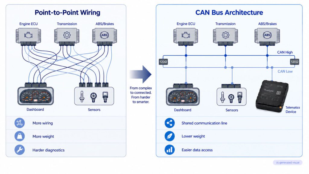
Before the advent of modern automotive electronics, vehicles relied on point-to-point wiring systems. Every component needed its own dedicated copper wire to communicate with another component. As manufacturers began adding more electronic control units to vehicles for safety, comfort, and emission control, the amount of wiring grew exponentially. By the early 1980s, cars were weighed down by miles of bulky, expensive, and heavy wiring harnesses that were incredibly difficult to troubleshoot.
To address this developing issue, Bosch created the Controller Area Network in the mid-1980s. Instead of a complex network of connections, they implemented a single, shared CAN bus system. This discovery allowed numerous controllers to send and receive CAN bus data via a single pair of cables. By removing miles of redundant wiring, CAN bus technology significantly reduced vehicle weight, lowered manufacturing costs, and increased system reliability. Currently, it is the industry standard for all commercial and passenger cars.
How Does CAN Bus Work?
To understand how the network operates, think of it as a broadcast radio station. Instead of sending a private message from one specific unit to another, a controller broadcasts its CAN bus data onto the network for all other units to hear. Each connected device continuously listens to the network and decides whether the broadcasted information is relevant to its own operations.
Every broadcasted packet of information is called a CAN message, or a frame. A standard frame contains several critical components:
- Message identifier. This unique ID determines the message’s priority and specifies what the data represents, such as engine speed or fluid temperature.
- Data length code. This specifies the exact size of the data being transmitted.
- The data field. This contains the actual CAN bus data being transferred.
The physical communication protocol uses a differential voltage system over two wires, CAN High and CAN Low. The CAN bus signal operates by measuring the difference in signal level between these two lines, providing exceptional resistance to electrical noise and interference. The effective CAN range and transmission speed depend on network topology, ensuring that critical safety messages always take precedence.
Because vehicles from different manufacturers format this data differently, a Telematics system often requires a CAN bus decoder to interpret the raw binary signals. Our comprehensive guide can help you understand how to decode CAN bus messages.
Types of CAN Bus: High-Speed vs. CAN FD
As automotive technology has grown, so has the underlying CAN protocol to meet the demands of data-intensive applications. Modern cars typically use two basic types of this network architecture to transmit CAN bus data:
- High-speed CAN. This is the traditional standard utilized for critical powertrain, braking, and safety systems. It supports data transfer rates up to 1 Mbps. High-Speed CAN ensures that time-sensitive commands, such as airbag deployment or anti-lock braking adjustments, are delivered with minimal latency.
- CAN FD (flexible data-rate). As modern vehicles and electric vehicles (EVs) require significantly higher bandwidth, CAN FD was introduced as the next-generation protocol. It increases data transfer speeds up to 5 Mbps or more and expands the data field payload size. This allows manufacturers to transmit more complex CAN bus data without increasing the vehicle’s physical wiring footprint.
Critical Protocols for Telematics: J1939 and OBD-II
While the CAN bus acts as the physical hardware and electrical cable network, vehicles need a shared language to make sense of the data flowing through those wires. This is where higher-layer protocols come into play. For fleet telematics, the two most critical standards are J1939 and OBD-II.
- SAE J1939 protocol. The J1939 protocol is the standard language for heavy-duty vehicles, buses, construction equipment, and agricultural machinery. It specifies the format of CAN bus data for engine characteristics, transmission status, and diagnostic codes. This protocol is critical for commercial fleet management since it enables telematics devices to read standardized engine data from several vehicle brands.
- OBD-II. The OBD-II standard is the diagnostic procedure required in passenger automobiles and light commercial vehicles. Its primary focus is on emissions control and vehicle diagnostics. Fleet managers that use light commercial vehicles rely on OBD-II characteristics to monitor vehicle health and emissions compliance.
CAN Bus vs. LIN Bus: What’s the Difference?
Not every component in a vehicle requires the high-speed capabilities of a Controller Area Network. To optimize manufacturing budgets, automotive engineers often pair the primary network with a secondary system called the LIN Bus (Local Interconnect Network).
Bandwidth and performance. Any ECU can communicate at any moment using the main CAN protocol, which is intended for high-speed, multi-master communication. LIN, on the other hand, uses a single-wire, single-master design and operates at somewhat slower speeds, typically up to 20 kbps.
Application and cost. Compared to the CAN bus technology, the LIN bus is far less expensive. When high-speed data transmission is not required, it is used for basic, non-essential comfort components. For instance, the main network can handle mission-critical vehicle data, while local features such as power windows, seat adjustments, side mirrors, and windshield wipers operate on a LIN bus.
The Business Value: Why Your Fleet Needs CAN Bus Data
Managing fleet operations is radically transformed when a professional telematics system is integrated with your vehicle’s internal network. Operators have access to extremely accurate CAN bus data that boosts productivity rather than depending on conjecture.
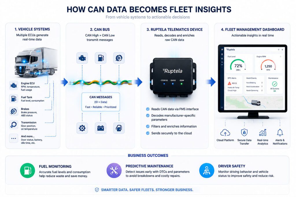
- Accurate fuel monitoring. Traditional fuel tracking often relies on erroneous dashboard readings or manual fuel receipts. Fleet managers may see exact fuel usage, fuel levels, and idle waste in real time by retrieving bus data straight from the engine control units.
- Predictive maintenance through vehicle diagnostics. Waiting for a breakdown to happen is expensive. Accessing the network enables a GPS tracking device to read Diagnostic Trouble Codes (DTCs) as they appear. This allows fleet managers to schedule maintenance proactively, preventing minor issues from escalating into costly engine failures.
- Enhanced driver safety. Fleet managers can keep an eye on severe braking patterns, forceful acceleration, and engine RPM in real time. Monitoring these signals reduces overall insurance risk, detects risky driving behaviors, and reduces component wear and tear.
How to Safely Access CAN Bus Data
Extracting this valuable information requires specialized hardware. Tapping directly into a vehicle’s factory wiring with traditional splicing methods can be highly risky. It can void manufacturer warranties, cause electrical shorts, or disrupt critical vehicle communication systems.
Ruptela offers advanced, non-invasive hardware solutions to eliminate these risks:
- Ruptela’s contactless CAN readers allow fleet operators to read data directly through the wire insulation using magnetic induction. This method ensures that the factory wiring remains completely untouched, preserving vehicle warranties while maintaining data integrity.
- Our advanced HCV5 and LCV5 tracking devices connect seamlessly to vehicle networks, including the standard FMS Interface. These devices automatically translate complex raw CAN bus data into clear, actionable insights on your fleet management dashboard.
Conclusion
At its core, the CAN bus is what makes truly smart logistics possible. Pulling data straight from your vehicles moves fleet management away from firefighting everyday emergencies and toward making calm, data-backed operational decisions. Whether you are trying to rein in fuel costs, keep trucks out of the repair shop, or protect your drivers on the road, everything you need to know is already being calculated right inside the vehicle.
Getting to that data does not have to be a headache. If you want to see exactly what parameters your vehicles can share, get in touch with the Ruptela team. We can help you run a quick fleet data audit to show you how our tracking hardware can bring clear value to your operations or your partners’ businesses.